2021年1月31日 星期日

The Advantages of High Voltage Ceramic Capacitors compared with film capacitor

 High voltage proof. Voltage Proof Test is to test whether the voltage at both ends of the capacitor lead can reach its corresponding withstand voltage standard and specified standard. Normally for Film capacitors, the voltage proof is 1.2UR, while high voltage ceramic capacitors can reach 2UR.

The Advantages of High Voltage Ceramic Capacitors compared with film capacitor

Smaller capacity. Compared with a film capacitor, a high voltage ceramic capacitor can achieve a small capacity. For regular models of film capacitor CBB21, the smallest capacity is 0.1uf, while high voltage ceramic capacitors can achieve 0.5pf and 1pf.

Smaller pitch. High voltage ceramic voltage can achieve a small pitch. For film capacitors, the pitches for regular models are as follow, 7.5mm, 10mm, 15mm, 20mm, 22.5mm, 27.5mm. The pitch is normally quite larger, while the pitch of high voltage ceramic capacitors can be 2.5mm, 5mm, 7.5mm.

The Advantages of High Voltage Ceramic Capacitors compared with film capacitor

JEC is a professional manufacturer in China for more than 30 years. Our safety capacitors receive all safety certifications we mentioned above from industry powers. We have a strict quality control system, please be rest assured. So if you’re interested in our products, welcome to contact us, we’re here 24 hours online waiting for you. 

The Advantages of High Voltage Ceramic Capacitors compared with film capacitor

2021年1月18日 星期一

What Is a Varistor?

 A "varistor" is a resistance device with non-linear volt-ampere characteristics. It is mainly used to clamp the voltage when the circuit is subjected to overvoltage and absorb excess current to protect sensitive devices. The resistor body material of the varistor is a semiconductor, which is a voltage-limiting protection device. Using the non-linear characteristics of the varistor, when an overvoltage occurs between the two poles of the varistor, the varistor can clamp the voltage to a relatively fixed voltage value, thereby realizing the protection of the subsequent circuit. The main parameters of the varistor are varistor voltage, current capacity, junction capacitance, response time, etc.

Varistor

1.Working principle of the varistor

When the voltage applied to the varistor is lower than its threshold, the current flowing through it is extremely small, which is equivalent to a resistor with infinite resistance. In other words, when the voltage applied to it is lower than its threshold, it is equivalent to an off-state switch.

When the voltage applied to the varistor exceeds its threshold, the current flowing through it increases sharply, which is equivalent to a resistor with infinite resistance. In other words, when the voltage applied to it is higher than its threshold, it is equivalent to a closed switch

2.Precautions for varistor

(1) It must be ensured that the continuous working voltage will not exceed the maximum allowable value when the voltage fluctuation is the largest, otherwise the service life of the varistor will be shortened;

(2) When a varistor is used between the power line and the ground, sometimes the voltage between the line and the ground rises due to poor grounding. Therefore, a varistor with a higher nominal voltage than the line-to-line use is usually used.

The failure mode of the varistor is usually a short circuit. In order to prevent the failure of the varistor from causing a short circuit of the power supply and catching fire, a temperature fuse or thermal release mechanism can be connected in series with each varistor. The temperature fuse should have a good thermal coupling with the varistor. When the varistor fails (high impedance short circuit), the heat generated by it will fuse the temperature fuse, thereby separating the failed varistor from the circuit and ensuring the equipment Security. When a higher power frequency temporary overvoltage acts on the varistor, it may cause the varistor to break down and short-circuit (low impedance short circuit) instantaneously, and the temperature fuse is too late to fuse, or it may catch fire. In order to avoid this phenomenon, an impact-resistant power frequency fuse can be connected in series with each varistor (single-use power frequency fuse may not blow when aging failure). The varistor can also be used in series with the ceramic gas discharge tube. The ceramic gas discharge tube does not conduct during normal operation, and the varistor has no leakage current, which can greatly extend the service life; when it is impacted by a surge, the ceramic gas discharge tube is the first to hit Then, the surge voltage is limited by the varistor. The total residual voltage is the sum of the two, which increases slightly (tens of volts); after the impact, the discharge tube cannot maintain conduction due to the varistor limiting the current The arc is extinguished and the normal working state is restored; when the varistor fails in a short circuit, the ceramic gas discharge tube will quickly fail due to the large power frequency current flowing through the ceramic gas discharge tube, but most of its failure modes are open circuits, so it is not easy to cause a fire.

We are varistor suppliers. Please feel free to contact us.

2021年1月7日 星期四

Varistor


What is a varistor?

varistor is a voltage-dependent resistor(VDR). The resistance of a varistor is variable and depends on the voltage applied. The word is derived from the "variable resistor. As the voltage increases, their resistance decreases. If the voltage is too high, its resistance will drop sharply. This behavior makes them suitable for protecting circuits during surges. The causes of the surge may include lightning and electrostatic discharge. The most common type of VDR is metal oxide varistor or MOV.

Definition

The varistor is a nonlinear binary semiconductor whose resistance decreases with the increase of voltage. Voltage-dependent resistors are commonly used as surge suppressors for sensitive circuits.

Characteristics

A resistor having a nonlinear change, depending on the voltage applied. Under nominal load conditions, the impedance is very high, but when the voltage threshold (the breakdown voltage) is exceeded, the impedance drops sharply to a low value. They are usually used to protect circuits from excessive transient voltages. When the circuit is exposed to high voltage transients, the varistor initiates conduction and the transient voltage clamp is brought to a safe level. The energy from the incoming surge is partially transmitted and partially absorbed, thereby protecting the circuit.

Varistor


The most common type is MOV or metal oxide varistor. They consist of sintered substrates of zinc oxide (ZnO) grains. Grain boundaries provide PN junction semiconductor characteristics, similar to diode junctions. The matrix of randomly oriented grains can be compared with large diode networks in series and parallel. When a low voltage is applied, the current due to the reverse leakage through the junction is very small. However, when a high voltage is applied that exceeds the breakdown voltage, an avalanche breakdown occurs and a large current flows through the junction. This behavior leads to nonlinear current-voltage characteristics.

The construction of the varistor

A varistor is formed when a crystal of silicon carbide or metal oxide is pressed into a ceramic material.

The material is then dried and sintered at a high temperature. The electrical properties of the equipment depend on the temperature and atmospheric conditions provided.

For good electrical contact, the contact point of the material is metalized with silver or copper. Then lead is then welded to the contact and the varistor is supplied and coded.

Application field

The nonlinear characteristics of varistors make them ideal for use as surge protectors. The source of high voltage transients may be an electrostatic or inductive discharge from a motor or transformer, such as a lightning strike. For example, they are commonly used for surge protectors on power panels. A special type of low capacitance protects communication lines. These VDRS are available for a variety of applications, including:

Telephone and other communication line protection

Transient suppression of radio communication equipment

Surge protector power panel

Surge protector for the cable TV system

Power protection

Microprocessor protection

Electronic equipment protection

Low-pressure plate level protection

Transient voltage surge suppressor (TVSS)

Automobile electronic protection

Industrial high energy exchange protection

Advantages of varistor

It provides excellent overpressure protection.

Because it does not show polarity effects, it is easy to achieve bidirectionally.

Disadvantages of varistor

This is expensive equipment.

We are Varistor Suppliers. Please feel free to contact us.

2020年12月25日 星期五

Metal Oxide Varistor, MOV: Voltage Dependent Resistance

 Metal oxide varistors are used for transient protection of electronic circuits.

A varistor can be considered a form of resistance, where the resistance changes significantly with the applied voltage. The most common types of varistors use metal oxides, so they are often referred to as metal oxide varistors or MOVs for short.

Considering that their resistance depends on the applied voltage, they can also be referred to as voltage-dependent resistors.

Their more familiar name varistor comes from the fact that these components are "variable-resistors", that is, the varistor is an acronym for two words.


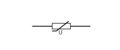
Varistor symbol


You can see that the varistor circuit symbol is very similar to the thermistor. It consists of a rectangular basic resistor symbol with a rectangle that crosses the diagonal and a small additional cross-section parallel to the body of the resistor symbol. This shows the non-linear characteristics of the varistor.

Varistor Circuit Symbol

Varistor Circuit Symbol

Although some other symbols may sometimes be used, the symbols shown are the most widely used and have been maintained under common standards.


Basic knowledge of varistor


The key characteristic of a mov varistor is that when a low voltage is applied across the varistor, it has a higher resistance, and for a higher voltage, the varistor will drop. Cause the varistor to conduct. As a result, they can be used for surge protection.

Select the varistor so that it does not conduct to the normally applied voltage, but select its conduction voltage so that the device starts to conduct above the normally applied voltage. In this way, any large transient voltage will be short-circuited and dissipated, thereby protecting the device.

There are two main varistor variants:

  • Ceramic/metal oxide varistor: This form of a varistor is the most widely used and is a form often mentioned when the term "varistor" is stated. Varistors are bidirectional, based on ceramics or metal oxides. As a result, this form of device is often referred to as a metal oxide varistor or MOV.

  • Diode varistor: This type of structure uses the characteristics of a diode to provide variable resistance. If only a single diode is used, it only works in one direction, but back-to-back diodes are used to provide bidirectional variable resistance characteristics. When an ordinary diode is used for protection, it is usually not called a varistor.


Varistor operation


Varistors are used in many fields and are usually used for surge protection across the line to be protected or in many areas from the line to the ground. Under normal conditions, they consume very little current, but when there is a surge, the voltage will rise above the knee or above the clamp voltage and will absorb the current, thereby eliminating the surge and protecting the equipment. The actual surge is absorbed by the varistor and part of it is taken away.

Metal oxide and silicon carbide varistors work because of the grain boundaries between the grains of the material act as small PN junctions. The whole assembly is like a large number of small diodes in series and parallel. When a low voltage is applied, since the junction is reverse biased and the only current is leakage current, current rarely flows. When a surge exceeding the clamping voltage appears across the device, the diode will undergo an avalanche breakdown, and a large current can flow through the device.

Varistors are only suitable for short-term pulses, not for continuous surges. Their size limits the power they can dissipate. Exceeding the rated time or voltage may cause the equipment to burn out, or in extreme cases, they may explode when the energy that needs to be dissipated is too high. Therefore, it is very important to operate them within the rated range.

It should also be noted that a metal oxide varistor (MOV) subjected to repeated surges may slightly change its performance and reduce its performance. After they experience a surge, the clamping voltage will drop a bit, which will eventually cause its damage.

Due to this failure mode, the MOV is usually connected in series with a thermal switch/fuse, and if too much current is consumed, the switch will activate.

mov varistor

MOV Varistor

Varistor specifications


When choosing a varistor for a given application, many parameters need to be considered. Some key move electronics specifications are listed below:

  • Clamping voltage: The varistor starts to show a voltage that is clearly turned on.

  • Rated voltage: This voltage (expressed as AC or DC) is the maximum voltage at which the device can be used. It is usually best to have a good margin between the rated voltage and the operating voltage, although this needs to be balanced with the clamping voltage and the required protection level.

  • Peak current: This is the maximum current that the device can handle. It can be expressed as the current at a given time.

  • Maximum pulse energy: This is the maximum pulse energy that the device can dissipate, in joules. The rated energy of a varistor is usually defined using standardized transients. Transients are expressed in x/y format, where x is the time for the transient to rise and y is the time to reach half of its peak value. Typical formats are 8/20 and 10/1000.

  • Response time: This is the time when the varistor starts to conduct after the pulse is applied. In many cases, this is not a problem. The typical value is sub 100nS.

  • Capacitance: The metal oxide varistor has a relatively high capacitance in the entire device. Although this may not be a problem for low-frequency applications, when it is used with data-carrying lines, etc., problems may arise. Therefore, it is necessary to check the capacitance value across the device of any circuit that may cause noise. problem. Although a low capacitance version can be used, the capacitance level of a typical metal oxide varistor may be between 100 and 1000 pF.

  • Standby current: The standby current is the current level drawn by the varistor when it is lower than the clamping voltage. Generally, this current will be specified at a given operating voltage across the device.


Varistor applications


Typical areas where varistors are used include:

  • Surge protection power adapter and power strip

  • Telephone and other communication lines

  • Power supply-the power supply usually connected to the main power cord

  • General electronic equipment protection

  • Automotive Electronics-Automotive electronics are notorious for having many spikes on power lines

  • Industrial high-energy AC line protection

Varistors are also used as microwave mixers in some cases for modulation, detection, and frequency conversion, although this is not a standard application.

Varistors can provide important protection for electronic circuits that may be affected by pulses and voltage spikes. They can transfer energy to the ground to protect equipment. These varistors are used in many projects, such as surge protection main sockets. They are used to protect computers and other equipment that may be affected by power surges and spikes.


2020年12月12日 星期六

Selection Guide for High Voltage Ceramic Capacitors

 Just as the name implies, high voltage ceramic capacitors refer to the capacitors that apply to high voltage circuits, so it requires good withstand voltage performance. Normally it’s above 1kv or 10kv. Below three tips can help you select a suitable model of high voltage capacitor more quickly.

 Selection Guide for High Voltage Ceramic Capacitors


1) Capacitance and Tolerance


Select the capacity by the specified nominal value on the capacitor. As for the tolerance, there are various ranks, when applying to low-frequency coupling circuits, decoupling circuits, power supply filtering circuits, etc., we can choose tolerance of 5%, 10%, and 20%. But for those applied to the oscillation circuit, delay circuit, and tone control circuit, it requires higher precision in capacitance. Various filters and networks even require much higher precision.

 Selection Guide for High Voltage Ceramic Capacitors


2) Withstand Voltage


To ensure the normal operation of high voltage capacitors, the withstand voltage we select should be higher than its actual working voltage, normally we choose those withstand voltage is more than twice of the actual working voltage.

 Selection Guide for High Voltage Ceramic Capacitors


3) Temperature Coefficient, High-Frequency Characteristics, and Other Parameters


When applying to oscillating circuits, like the oscillating elements, the phase-shifting network element, filter, etc., to ensure its performance, we should choose the one with a low-temperature coefficient. When applying to high-frequency circuits, due to the influence of its inductance, lead inductance, and high-frequency loss, the performance of high voltage capacitors will be poor.

We JYH HSU(JEC) Electronics LTD. is a professional manufacturer in electronic components for more than 30 years. We pass ISO 9001:2015 quality management system. Our safety capacitors(including X capacitors and Y capacitors) and varistors obtain a lot of safety certifications from industry powers including VDE in Germany, ENEC in EU, UL in US, CUL in Canada, KC in Korea, CQC in China, etc, we can supply quality-assured products, professional suggestion and excellent service to our customers. So if you’re interested in any electronic components, please free free to contact us. We’re here 24 hours online waiting for you!


2020年11月26日 星期四

Some Things that Should Be Paid Attention to When Using Ntc Thermistor

 NTC thermistor is similar to varistor. It is a very important circuit protection electronic component in the circuit. There are some details that need to be paid attention to when using it, otherwise it is easy to cause damage to the NTC thermistor.

1. Pay attention to the working temperature of NTC thermistor.

Never use the NTC thermistor outside the operating temperature range. The operating temperature of φ5, φ7, φ9, and φ11 series is -40~+150℃; the operating temperature of φ13, φ15, and φ20 series is -40~+200℃.

2. Please pay attention to use NTC thermistor under rated power condition.

The maximum rated power of each specification is: φ5-0.7W, φ7-1.2W, φ9-1.9W, φ11-2.3W, φ13-3W, φ15-3.5W, φ20-4W.

3. Precautions for use in high temperature and high humidity environments.

If the thermistor needs to be used in a high temperature and high humidity environment, a sheathed thermistor should be used, and the protective cover should be used to close the part exposed to the environment (water, moisture), and the opening of the sheath will not directly touch Water and steam.


4. Cannot be used in hazardous gas and liquid environment.

Do not use it in a corrosive gas environment or in an environment where it will come into contact with electrolyte liquid, salt water, acid, alkali, or organic solvent.

5. Protect the wires.

Do not excessively stretch or bend the wire, and do not apply excessive vibration, shock, and pressure.

6. Keep away from heating electronic components.

Avoid installing electronic components that are easy to heat around the power NTC thermistor. It is recommended to use products with higher leads on the upper part of the bent leg, and use NTC thermistors higher than other components on the circuit board to prevent heat from affecting the normal operation of other components.

We are thermistor manufacturers, if you are interested in our products, please feel free to contact us.

2020年11月18日 星期三

How to Measure the Quality of the Thermistor?

 Due to the unique performance of semiconductor thermistors, it can not only be used as measuring components (such as measuring temperature, flow, liquid level, etc.), but also as control components (such as thermal switches, current limiters) and circuit compensation element. Thermistors are widely used in various fields such as household appliances, electric power industry, communications, military science, aerospace, etc., and their development prospects are extremely broad.

When testing the thermistor, first test its resistance in an indoor environment, and then hold the product with your hand to test to see if its resistance becomes smaller. If it changes, it means normal, otherwise, it is abnormal. Note: Special instruments should be used for accurate measurement during testing. The following thermistor China supplier introduces some measurement methods.

1. Room temperature detection

Set the multimeter to the resistance file, and the two meters touch the two pins of the thermistor. The reading of the multimeter is the resistance value of the thermistor under test at room temperature. On the premise of correct selection of the resistance file, if the reading is o or infinity, it means that the thermistor has been damaged.

2. High-temperature detection

Use an electric soldering iron as a heat source close to the thermistor. If the resistance displayed by the multimeter changes significantly from the resistance at room temperature, remove the soldering iron and the negative value will return to the negative value at room temperature, indicating that the thermistor is good.

3. Low-temperature detection

Clamp the two pins of the thermistor with a multimeter clamp, and put the thermistor into the refrigerator. Normally, the negative value displayed by the thermistor with a negative temperature coefficient is significantly larger than the negative value at room temperature; for the thermal resistance with a positive temperature coefficient, the resistance value displayed by the multimeter is significantly lower than the negative value at room temperature.

4. Heating method

Connect the two lead wires of the thermistor with the resistance gear of a multimeter, and then use a hot electric soldering iron (20W is fine) to heat the thermistor (close to the thermistor). For the PTC type thermistor, as the temperature increases, the resistance value should increase; for the NTC type thermistor, as the temperature increases, the resistance value should decrease. If the thermistor is heated, its resistance does not change, indicating that the thermistor is damaged.

5. Multimeter measurement method

Positive temperature coefficient thermistor (PTC) detection
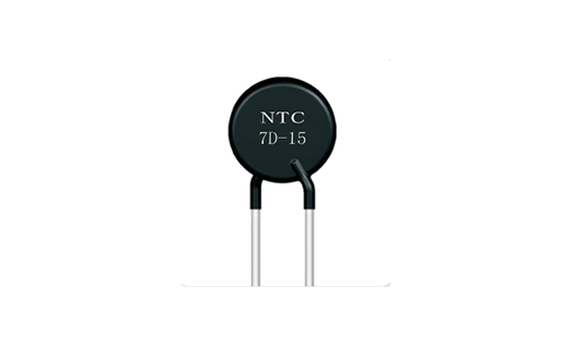
Thermistor

Thermistor

When testing, the multimeter is adjusted to R×1 gear, which can be divided into two steps:

(1) Normal temperature detection (indoor temperature is close to 25℃): The actual resistance value of the two pins of the PTC thermistor is measured by touching the two test leads to the two pins of the PTC thermistor, and compared with the nominal resistance value. The difference between the two is within ±2Ω. normal. If the actual resistance value differs too much from the nominal resistance value, it means that its performance is poor or damaged.

(2) Heating test: On the basis of the normal temperature test, the second step of the test—heating test can be carried out. Put a heat source (such as electric soldering iron) close to the PTC thermistor to heat it, and monitor its resistance with a multimeter. Whether the value increases with the increase in temperature, if it is, it means that the thermistor is normal. If there is no change in the resistance value, it means that its performance has deteriorated and cannot be used continuously. Be careful not to put the heat source too close to the PTC thermistor or directly touch the thermistor to prevent it from being burned.

Negative temperature coefficient thermistor (NTC) detection

(1) Measuring the nominal resistance value Rt: The method of measuring NTC thermistor with a multimeter is the same as the method of measuring ordinary fixed resistance, that is, according to the nominal resistance of the NTC thermistor, selecting the appropriate electrical barrier can directly measure the Rt Actual value. But because NTC thermistor is very sensitive to temperature, the following points should be paid attention to when testing: ARt is measured by the manufacturer when the ambient temperature is 25℃, so when measuring Rt with a multimeter, the ambient temperature should be close to 25 It is carried out at ℃ to ensure the reliability of the test. B. The measured power must not exceed the specified value to avoid measurement errors caused by current heating effects. C pays attention to correct operation. During the test, do not pinch the thermistor body with your hands to prevent the body temperature from affecting the test.

(2) Estimate the temperature coefficient αt: the first measure the resistance value Rt1 at room temperature t1, and then use an electric soldering iron as a heat source, close to the thermistor Rt, measure the resistance value RT2, and use a thermometer to measure the thermistor RT at this time The average surface temperature t2 is then calculated.



 The Role of Film Capacitors in Filtering Circuits There are many types and models of capacitors, and film capacitors are one of the them. F...